Cable Form Factors and Connector Types
SFP (Small Form Factor Pluggable) – A transceiver or cable with a one or two lanes (channel) in each direction. All cables and transceivers commonly used in datacenters are bidirectional.
SFP+ denotes the 10 – 14 Gb/s type of AOC/transceivers, while SFP28 is the notation for the 25-28 Gb/s products with an SFP form factor. The noted data rate is the data rate in each direction.
SFP-DD, a double-density version of SFP, with 2 lanes in a form factor with same width as the SFP is defined, but are not part of Nvidia’s product portfolio at the time of release of this paper.
SFP transceivers are part of the Ethernet architecture, but not used in InfiniBand systems.
QSFP (Quad Small Form Factor Pluggable) – A bidirectional transceiver or cable with 4 lanes in each direction.
Standards: Electrical pinout, memory registers, and mechanical dimensions for both SFP and QSFP devices are defined in the public MSA (Multi-source Agreement) standards available at: www.snia.org/sff/specifications.
QSFP+ denotes cables/transceivers for 4 x (10 – 14) Gb/s applications, while QSFP28 denotes the 4 x (24…28) = 100 Gb/s product range with QSFP form factor, used for InfiniBand EDR 100Gb/s ports and 100Gb/s Ethernet (100GbE) ports. The QSFP28 interface is specified in SFF-8679.
QSFP56 denotes 4 x (50…56) Gb/s in a QSFP form factor. This form factor is used for InfiniBand HDR 200Gb/s and 200/400GbE Ethernet cables/transceivers in Nvidia’s portfolio.
QSFP-DD refers to a double-density version of the QSFP transceiver supporting 200 GbE and 400 GbE Ethernet. It employs 8 lanes operating at up to 25Gb/s NRZ modulation or 50Gb/s PAM4 modulation. QSFP-DD cables will in general not work in standard QSFP cages, but switches/NICs with QSFP-DD cages may support the older QSFP transceivers/cables.
OSFP (Octal Small Form Factor Pluggable) is wider and longer than QSFP and accommodates 8 lanes side-by-side. This form factor is used for 200/400/800G transceivers in Nvidia’s InfiniBand NDR portfolio. More info on https://osfpmsa.org
AOC (Active Optical Cable) – An optical fiber cable with an optical transceiver with the fibers bonded inside and not removable. The optical transceiver converts the host electrical signals into light pulses and back. Bonding the fiber inside means the AOC only needs to be tested electrically and eliminates the costly optical testing.
Transceiver (transmitter and receiver) is a converter with an electrical connector in one end and optical connector in the other end. It can have one or more parallel lanes in each direction (transmit and receive).
Transceiver or AOC? – You can argue that two transceivers connected with a patch cable replace an AOC. However, if you don’t have cleaning tools and experience with optical connectors, it is safer to use an AOC where the optical cable is fixed inside the ‘connector’. The AOC’s ‘connectors’ are actually similar to detachable transceivers, but they work as a kit with a well-known transceiver at the other end. AOCs don’t have any issue with multi-vendor interoperability. Nevertheless, it is easier to replace a pair of transceivers than an AOC since you don’t have to install a new cable as the cable is already in place.
Traditionally, AOCs are more common in InfiniBand installations, while transceivers with patch cables are more common in Ethernet systems with structured cabling.
DAC (Direct Attached Copper) cable or PCC (Passive Copper Cable) – A high-speed electrical cable with an SFP or QSFP connector in each end, but no active components in the RF connections. The term ‘passive’ means that there is no active processing of the electrical signal. The DACs still have an EEPROM, a memory chip in each end, so the host system can read which type of cable is plugged in, and how much attenuation it should expect.
Cable/Transceiver Form Factors and Connector Definitions
|
Definition |
Photo |
|
DAC (Direct Attach Copper) cable with QSFP connector |

|
|
DAC with SFP connector |

|
|
AOC (Active Optical Cable) with QSFP connector |

|
|
QSA (QSFP to SFP Adapter) |

|
|
QSFP transceiver QSFP28 Transceiver for 100G transmission QSFP56 Transceiver for 200G transmission QSFP112 Transceiver for 400G transmission |


|
|
QSFP-DD transceiver 8 lane 200/400G transceiver |

|
|
OSFP transceiver Single/Dual 8 lane 1/2 x 400G transceiver |

|
|
SFP transceivers 25G SFP28 Transceiver (~1 W) |

|
QSFP56/SFP56 has 4/1-channels like the QSFP28/SFP28 generation but twice the data rate.
Same Duplex LC and MPO-12 optical connector as QSFP28/SFP28 generation
QSFP56 offers more space and thermal dissipation capacity
50G PAM4 doubles the data rate
SFP56 ports accept SFP28 devices; QSFP56 ports accept QSFP28 devices
QSFP28/SFP28 ports will NOT accept newer QSFP56/SFP56 devices
SFP-DD ports will accept SFP+, SFP28, and SFP56 devices
SFP-DD is a 2-channel device, and hence requires a new optical connector scheme. Two types are currently (2019) supported by the SFP-DD MSA: Corning/US Conec MDC, and Senko SN.
MMF (Multi-Mode Fiber) – The type of fiber used for VCSEL (Vertical Cavity Surface Emitting Laser) based transmission, normally operating at 850 nm wavelength. Its maximum reach is 100 m for 25 Gb/s line rates. Multi-mode fiber has a large light carrying core (50 µm) and matches the diameter of VCSEL lasers and PIN detectors making assembly very low cost.
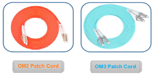
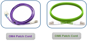
OM2, OM3, OM4 (Optical Multi-mode) are classifications of MMF for different reach and speeds. Higher number indicates lower degradation of the optical signal, and longer reach. MMF cables commonly have the colors shown below, but standards are not fully consistent.
OM2 – orange – used for data rates at 1-14 Gb/s, 62.5 µm fiber core diameter
OM3 – aqua – 70 m reach for 25/100 Gb/s transceivers, 50 µm core diameter
OM4 – aqua – 100 m reach for 25/100 Gb/s transceivers, 50 µm core diameter
OM5 – aqua green – not commonly used (2023)
Multi-mode fiber patch cords
SMF (Single-Mode Fiber) – The type of fiber used for Indium Phosphide or Silicon Photonics based transceivers, operating at 1310 or 1550 nm wavelength. Single-mode fiber usually has a yellow jacket and can reach 100s of km. The tiny 7-9 µm light carrying core makes building single-mode optics much more expensive than multi-mode optics.
CWDM, WDM, DWDM, (Coarse Wavelength Division Multiplexing, Normal, Dense) – a technology for transmitting multiple optical signals through the same fiber. All signals have different wavelengths (colors). WDM transceivers make it possible to reduce the number of fibers in the link to two, one for transmit, and one for receive.
Dense WDM employs a very narrow 0.78 nm laser wavelength spacing used in single-mode links. The laser needs to be temperature controlled so these devices usually employ an electrical cooler – which adds cost.
Coarse WDM employs a wide 20 nm laser wavelength spacing used in single-mode links and because of the wide wavelength spacing does not require a cooler, so less expensive.
Short WDM (SWDM) employs 4 different wavelengths multi-mode VCSEL lasers.
PSM4 (Parallel Single-Mode 4 fiber) is the opposite of WDM in the sense that each signal is transferred in its own fiber. This requires 4 fibers in each direction but enables simpler transceiver design since all signals can have same wavelength and no optical MUX/DeMUX (AWG) is required and no TEC (Thermo Electric Cooler) to stabilize the laser wavelengths. PSM4 is a MSA (Multi Source Agreement), i.e. a standard supported by a number of transceiver vendors.
Transceivers are classified with data- rate and reach, governed by the IEEE Ethernet standards. For 100 - 400 Gb/s transceivers the most common definitions are:
100GBASE-CR4 – 100 Gb/s, standard for DAC cables (twisted pair) for short reaches, up to about 7 m.
100GBASE-SR4 –100 Gb/s, SR4=Short Reach (100 meters on OM4 multimode fiber), 4 fibers
100GBASE-LR4 – 100 Gb/s, LR=Long Reach (10 km using WDM on SMF), 2 fibers
100GBASE-ER4 – 100 Gb/s, ER=Extended Reach (30-40 km using WDM on SMF), 2 fibers
100GBASE-ZR – 100 Gb/s, ZR is not an IEEE standard, 80+ km reach.
200GBASE-CR4 – 200 Gb/s on DAC (passive copper) twisted pair cable, up to 3 m
200GBASE-SR4 – 200 Gb/s, SR4=Short Reach (100 meters on OM4 multimode fiber), 4 fibers
200GBASE-DR4 – 200 Gb/s, DR4 = 500 meters on single mode fibers, 4 fibers per direction
200GBASE-FR4 – 200 Gb/s, FR4 = 2 km, single mode fibers using WDM, 1 fiber per direction
200GBASE-LR4 – 200 Gb/s, LR4 = long reach, 10 km, single mode fibers using WDM, 1 fiber per direction
400GBASE-DR4 – 400 Gb/s, 500 meters on single mode fiber, 4 fibers each direction
400GBASE- FR4 – 400 Gb/s, WDM, 2 km on 1 single mode fiber/direction, 4 electrical lanes
400GBASE-FR8 – 400 Gb/s, WDM, 2 km on 1 single mode fiber/direction, 8 electrical lanes
All 200/400 Gb links use PAM4 signaling which implies that Forward Error Correction (FEC) is required.
The interface types listed above are examples for 100, 200, and 400 GbE links. The IEEE 802 standards define a wide range of standards for different Physical Media Devices (PMDs), see https://en.wikipedia.org/wiki/Terabit_Ethernet#200G_port_types. and PMD Naming Conventions figure below. Some of the transceiver types are not IEEE standards but separate industry MSAs (Multi-Source Agreements) usually formed by a leading transceiver company.PSM4, SWDM4, CWDM4 and 400G FR4 are examples.
PMD Naming Conventions
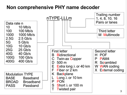
Ref. https://ieee802.org/3/cn/public/18_11/anslow_3cn_01_1118.pdf
In the Data rate block, 200G (200 Gb/s) was added after 2018 when the above figure was published.
High-speed cables make use of edge ‘gold-finger’ connectors on the electrical side which attaches to the host system (switch, network card on server/storage). On the optical side, the following connector types are the most common:
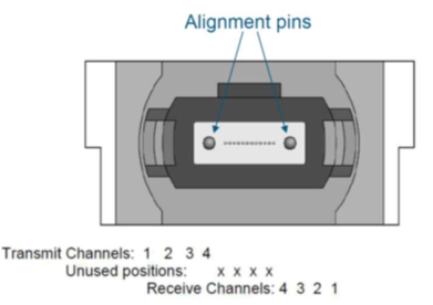
MPO (Multi-fiber Push On), is a connector standard supporting multiple rows with up to 12 fibers in each. A QSFP transceiver with MPO receptacle uses the outermost 4 positions on each side. The center 4 positions are not used.
Single-row MPO Connectors used in QSFP Transceivers
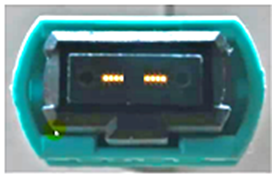
MTP connectors are a vendor specific proprietary high-precision version of MPO connectors.
The optical port in the parallel 2 x 4-lane QSFP optical transceiver is a male MPO connector with alignment pins, mating with fiber-optic cables with female MPO connector. The connector contains a 12-channel MT ferrule (allows to bundle multiple channels into a single connector).
QSFP28 Optical Receptacle and Channel Orientation for Male MPO Connector
Female MPO Cable Connector Optical Lane Assignment
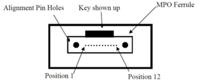
Reference: IEC specification IEC 61754-7.
LC connectors are used for both single-mode and multi-mode fibers and are used in both SFP and QSFP MSA transceivers.
Duplex LC Connector and SFP Transceiver with LC Receptacles
There are many other optical connector standards. MPO and LC are commonly used for data center patch cables and transceivers.
The choice of Optical patch cable depends on the type of transceivers you need to connect.
Transceivers and Cable Connectors
|
Transceiver |
Reach and Type |
Connector on Transceiver |
Connector on Patch Cable |
|
MMA2P00- MFM1T02A |
25G SR SFP 10G SR SFP 2 fiber multimode |
Multimode Duplex LC/UPC
|
Duplex LC/UPC 
|
|
MC2210411-SR4 MMA1B00-xxxx MMA1T00-VS |
40G SR4 QSFP 100G SR4 QSFP 200G SR4 QSFP 2x4 fiber multimode |
Multimode Male MPO/UPC (with pins) 
|
Female MPO/UPC (with holes) 
|
|
MMA1L20-AR |
25G LR SFP 2 fiber Single mode |
Single mode Duplex LC/UPC |
Duplex LC w single-mode fiber 
|
|
MC2210511-LR4 MMA1L30-CM MMA1L10-CR |
40G CWDM, QSFP, 100G CWDM, QSFP, 2km 100G LR4 QSFP 2 fiber Single mode |
Single mode Duplex LC/UPC 
|
|
|
MMS1C10-CM MMS4X00 |
PSM4, QSFP, 500m 2x4 fiber single mode |
Single mode MPO/APC (8 fiber, Angle polished connector) 
|
Female MPO/APC with single-mode fiber. The key is centered
|
|
Two 8-fiber Single mode in one unit |

|
||
|
T-DQ8FNS-N00 MMA4U00-WS-F |
QSFP-DD SR8 2x8 fiber Multi-mode |
Male MPO16/APC (16 fiber Angle Polished Connector) 
|
Female MPO16/APC with multi-mode fiber. The key is offset. 
|
|
MMA4Z00 |
OSFP SR8 |
Male MPO12/APC (12 fiber Angle Polished Connector) 
|
Female MPO12/APC with multi-mode fiber
|
Recently, NVIDIA devices with OSFP form factor have been expanded to work in both Ethernet and InfiniBand systems.
NV Link
A third type of application is NV Link (used in NVIDIA DGX systems). The DGX systems are equipped with either ConnectX-6 or ConnectX-7 HCAs (network adapters). Systems with ConnectX-6 adapters can use the MMA4U00-WS-F transceiver. Systems with ConnectX-7 adapters have OSFP connector and can use MMA4Z00 and MMS4X00 transceivers listed above.
UPC vs APC connectors
In the past, longer-reach single-mode applications like 100GBASE-LR4 allowed for greater insertion loss. With less-expensive transceivers entering the market comes a reduced insertion loss allowance. Compared to the 6.3 dB allowed for 100GBASE-LR4 which supports 100G up to 10 kilometers, the short-reach 100GBASE-DR applications up to 500 meters comes at just 3 dB. Just like 100G multimode applications, designers need to be aware of their loss budgets that could limit the number of connections in the channel.
With single-mode fiber and higher data rates, return loss is more of a concern. Too much light reflected back into the transmitter can cause bit errors and poor performance. The reflections can be significantly reduced using angled physical contact (APC) connectors, where an 8-degree angled end face causes reflected light to hit and be absorbed by the cladding.
Generally, there are some basic considerations related to the use of single-mode fiber. A single mode is more difficult to keep clean than multimode. A speck of dust on a 62.5 or 50 µm multimode fiber core blocks a lot less light than on a 9µm single-mode fiber core.
When inspecting APC single-mode connectors, you want to make sure to use an APC inspection probe tip designed to match the angle of the APC connector. This is required as part of the inspection equipment.
For APC connectors, note that not the entire end face of the connector is in contact with the cleaning device. It cleans the middle portion of the connector where the fibers are located and does not catch contamination at the outer parts.
While no damage will occur if you connect an APC connector to the input, you will get a warning about the received power being too low. To test products with APC connectors, you will need two hybrid UPC-to-APC cords and two APC-to-APC cords to make the connection. For Tier 2 OTDR testing, since reflections are absorbed by the cladding and return loss is very small when using APC connectors, the OTDRs will show APC connections as a non-reflective loss like a good fiber splice.
For 200GBASE-DR4 and 400GBASE-DR4 short-reach single mode applications, MPO connectors are in use as they require 8 fibers, with 4 sending and 4 receiving at 50 or 100 Gb/s. That’s where a tester like Fluke Networks’ MultiFiber Pro or Viavi’s Sidewinder with dedicated on-board MPO connector which scan all fibers simultaneously is highly recommended to avoid time-consuming use of MPO to LC fan-out cords to separate the multiple fibers into single fiber channels.
For testing single mode fiber systems, you also want to make sure you’re testing at both the 1310 and 1550nm wavelengths. Not only if these two wavelengths pass so will everything in between, but slight bends might not show up at the 1310 nm wavelength.
UPC vs APC connector
Connecting a server with QSFP network card/transceiver to a QSFP port in a switch
The fiber that connects with the transmitter’s lane 1 must end at receiver lane 1 at the far end of the cable. Position 1 of the MPO connector at the near end of the cable connects to position 12 of the opposite MPO connector.
Use a patch cable with MPO connectors at both ends, and with crossed connections as shown below.
MPO to MPO Patch Cable Fiber Position
|
Left Cord |
Connection |
Right Cord |
|
1 |
|
12 |
|
2 |
|
11 |
|
3 |
|
10 |
|
4 |
|
9 |
|
5 |
Not Connected |
8 |
|
6 |
Not Connected |
7 |
|
7 |
Not Connected |
6 |
|
8 |
Not Connected |
5 |
|
9 |
|
4 |
|
10 |
|
3 |
|
11 |
|
2 |
|
12 |
|
1 |
This is sometimes referred to as a ‘Type B cable’,
ref. https://www.flukenetworks.com/blog/cabling-chronicles/101-series-12-fiber-mpo-polarity
Multiple MPO patch cables can be connected in series, but each added connector pair increases modal dispersion in the link which again impairs performance. An odd number of ‘crosses’ must be used between transceivers at the two ends to get transmitters connected with receivers.
Connecting MPO Cables with an MPO adapter
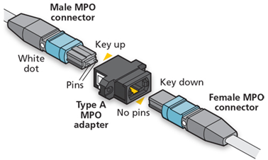
If two transceivers are to be directly connects, a “cross-over” fiber cable must be used to align the transmitters on one end to the receivers on the other end.
Connecting servers with SFP network card/transceivers to a QSFP port in a switch
A QSFP port and transceiver contains four independent transmit/receive pairs. I.e. you can connect 4 servers with SFP cards/transceivers to a single QSFP port in a switch. This enables connection of four 10GbE NICs to one 40GbE port, or four 25GbE NICs to one 100GbE port.
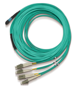
In either case you need an MPO to four Duplex LC splitter (breakout) cable. Either multi-mode or single-mode optics can be used depending on the reach needed.
Servers sharing QSFP Switch ports
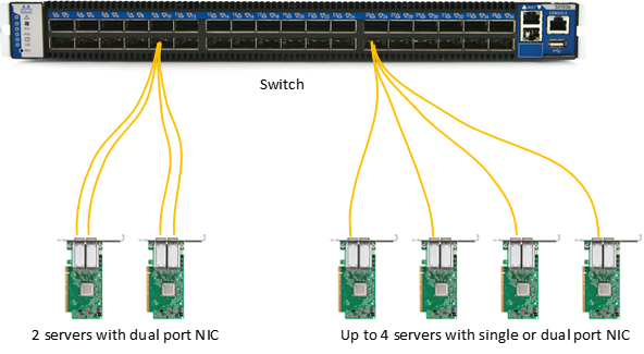
The QSFP ports of the switch must be configured to work in split mode, with the 4 lanes working in ‘split’ mode; that is, the lanes operate as independent channels instead of operating as a single logic port. This can be achieved with passive copper splitter cables (DACs) or with optical splitter cables. Switch ports (not NIC ports) can be configured to operate in split mode.
Optical transceivers for the optical solution are not shown in the figure above.
Splitter cable examples: 25/100 GbE
MCP7F00 – 100 Gb 1:4 splitter DAC, max 3 m
MCP7H00 – 100 Gb 1:2 splitter DAC, max 3 m
MFA7A20 – 100 Gb 1:2 optical splitter, up to 20 m long tails
MFA7A50 – 100 Gb 1:4 optical splitter, up to 30 m long tails
Splitter cable examples: 50/200 GbE
MCP7H50 – 200 Gb 1:2 optical splitter DAC, max 3 m
MFS1S50 – 200 Gb 1:2 optical splitter, up to 30 m long tails
MFS1S90 – 200 Gb 2:2 optical H-cable, up to 30 m long tails
Note 1: network adapter card ports cannot be split – only switch ports.
Note 2: The total number of ports that can be split with cables is based on the specific number of MACs inside the switch chip. See the switch documentation for specific configuration limits.
Optical splitter cables are available in the market for use between SR4 and SR transceivers.
InfiniBand
Port splitting/sharing a switch port across multiple servers was originally implemented for Ethernet, but is also available with the latest NDR generation of InfiniBand networking products. A wide variety of copper and optical cables have been developed for splitting 400/800G port capacity across 2 or 4 servers/hosts. Contact the NVICIA Networking team for more information on this topic.
Multi-mode splitter (breakout) cable
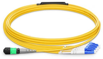
For longer reaches, a single-mode QSFP PSM4 transceiver can be connected to up to four NICs with LR transceivers using a single-mode splitter cable. Today, a common split is a 100G PSM4 split to 2x50G PSM4 transceivers used in large servers or storage systems.
Single-mode splitter (breakout) cable (not an NVIDIA product)
You cannot split the channels of a WDM transceiver using simple splitter cables. WDM transmitters use a single pair of fibers with the four channels carried on light of different wavelengths.
LinkX® is the product line brand for NVIDIA’s DAC, AOC and transceivers products that supports InfiniBand and Ethernet.
InfiniBand (IB) is a computer-communications standard used in high-performance computing that features very high throughput and very low latency. InfiniBand is commonly used in HPC (High-Performance Computing) and hyperscale datacenters. InfiniBand is promoted by the InfiniBand Trade Association (IBTA), http://www.infinibandta.org/. See InfiniBand: Introduction to InfiniBand for End Users for an introduction.
Ethernet (ETH) is a family of general computer networking technologies commonly used inside and outside datacenters. It comprises a wide number of standards, commonly referred to as IEEE 802.3, which is promoted by IEEE (www.ieee.org).
Form Factors, power classes, connector definitions and management interface specifications are found in https://www.snia.org/sff/specifications2.
The main differences between the two protocols are as follows:
InfiniBand links up to Nx25 Gb/s; generally, don’t use Forward Error Correction to minimize link latency. For higher data rates, FEC is a necessity.
CDR (Clock and Data Retiming) default state:
IB EDR: Clock/data recovery (CDR, or retiming) is bypassed/disabled except for AOCs 30 m or longer running Nx25 Gb/s or lower rates.
IB HDR: Clock/data recovery (retiming) is as well as FEC are necessary for error free transmission due to the physical nature of PAM4 signaling.
Ethernet 100G: The CDR is default on.
The CDR must be disabled to pass data at lower rates, for example 40 Gb/s.200/400 GbE (Ethernet) – CDR and FEC are both required for error free transmission. 25/100 GbE is supported but lower data rates are not generally supported.
Copper cables:
IB EDR: The cable length and related attenuation determines if the operation can be achieved without FEC.
Ethernet 25/100GbE: Reed Solomon Forward Error Correction or RS-FEC is enabled by default for cables denoted CA-25G-L which are longer than 3 m. FEC is not required for cables denoted CA-25G-N which are up to 3 m long.
The EEPROM memory map of QSFP28 (100 Gb/s cables/transceivers) is defined in specification SFF-8636 for 4-lane transceivers, and for SFP28 (25 Gb/s cables/transceivers) in SFF-8472 for 1-lane transceivers.
Management of transceivers with more than 4 lanes is defined in the Common Management Interface Standard (CMIS),
http://www.qsfp-dd.com/wp-content/uploads/2021/11/CMIS5p1.pdf
Transceivers with QSFP formfactor and 4 lanes can also be CMIS compatible. You need to read the memory map to tell if a given transceiver is the SFF or the CMIS type.
Memory map differences summary (informative):
A summary is given in IB Vol 2 Annex A3.2: InfiniBand vs. Ethernet Memory Map Differences – QSFP/QSFP+ https://cw.infinibandta.org/document/dl/8125 (membership required).
IB EDR loss budget (asymmetric): IB Vol 2 Annex A2.5 EDR Overall Link Budget for Linear Channels (informative)
Ethernet: IEEE 802.3 clause 92 – copper cables, clause 83 – Physical Medium Attachment (PMA) including CDRs
All LinkX® cables and transceivers for data rates up to InfiniBand EDR and 25/100 GbE (Ethernet) are tested in Nvidia end-to-end systems for pre-FEC BER of 1E-15 as part of our product qualification; more specifically, as part of the System Level Performance (SLP) test.
IB HDR, 200 GbE and higher data rates, cables and transceivers are different from previous generations. Due to the nature of physics of the PAM4 modulation used in these cables and transceivers, error-free transmission is only achievable with the use of FEC. This type of cables/transceivers are qualified at 1E-15 effective BER in Nvidia InfiniBand/Ethernet end-to-end systems.


